SanDisk
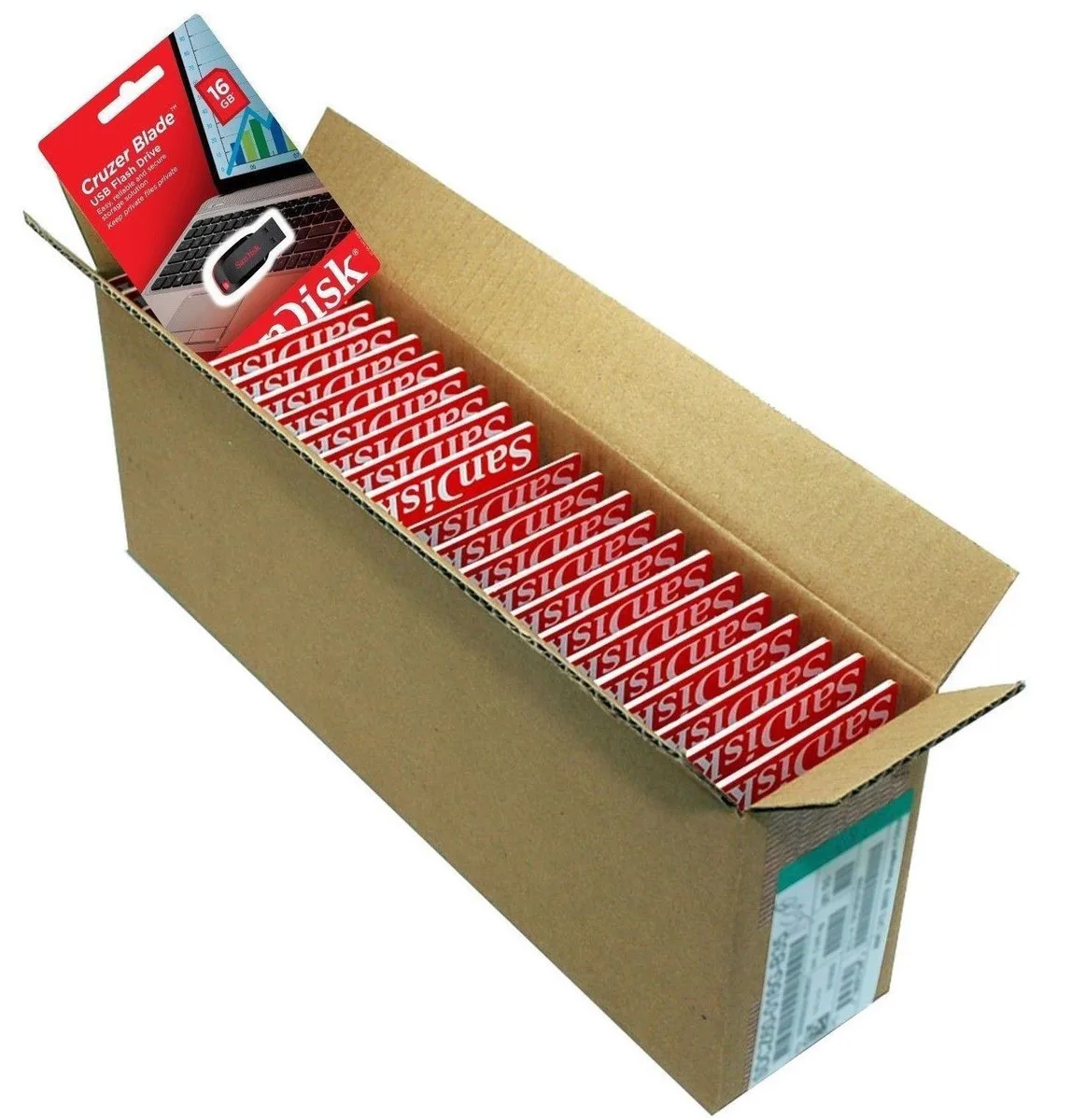
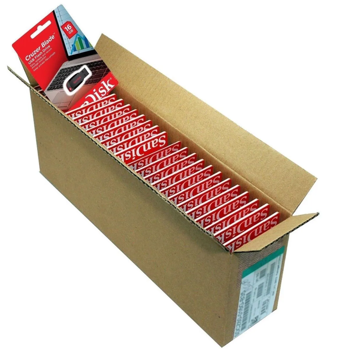
SanDisk Cruzer Blade 8 GB USB 2.0 USB flash drive Black SDCZ50-008G-B35
$391.99
0.00501157BTC
在庫あり


ProTechTrader
FM radio breakout covering 76–108 MHz with RDS/RBDS decoding, 3.3 V I²C or 3-wire interface, 3.5 mm jack uses headphone cable as antenna
The ProTechTrader PTT-Si4703 is a development board that adds FM radio reception to microcontroller projects. It serves as a pin-compatible replacement for the SparkFun WRL-12938 V13 board and is referenced in the Make: Radio educational book. Makers and students can use it with 3.3V Arduino, Raspberry Pi, AVR or ARM platforms to experiment with broadcast radio.
The Si4703 chip tunes the 76 to 108MHz FM band and processes both RDS and RBDS data signals. The module operates at 3.3V and communicates via a two-wire I2C interface at up to 400KHz or an optional three-wire system at up to 2.5MHz. Programmable de-emphasis supports 50µs and 70µs standards for regional broadcast compliance.
A 3.5mm audio jack provides the output; inserting headphones or a cable longer than three feet uses the lead as the antenna, so no external aerial is required. The board matches the V13 pinout with GND, 3.3V, SDIO, SCLK, SEN, RST, GPIO1 and GPIO2, though headers are not soldered. Note that the V13 layout swaps the 3.3V and GND positions compared to the older V11 WRL-10663 design.
| Brand | ProTechTrader |
|---|---|
| Model | PTT-Si4703 |
| Part Number | PTT-Si4703 |
Solder the supplied header pins to the board, then wire GND, 3.3V, SDIO, SCLK, SEN, RST, GP101 and GP102 to matching 3.3V logic pins on your Arduino or Raspberry Pi; note that the V13 layout swaps the 3.3V and GND positions compared to the older V11 board.
No periodic maintenance is needed; the board has no moving parts or consumable components, so only re-solder any header joints that become loose over time.
The cable must be longer than 3 feet to act as a sufficient antenna; shorter cables or no headphones connected will cause reception to degrade first during sustained listening.
同じ売り場の商品
同じ売り場、同じレジ — 8種類のコインと30分間のレートロック。
お支払いに使うコインと、価格表示に使う通貨です。
チェックアウト時にウォレットから送信されます。
表示のみ—カタログの価格は米ドル建てです。
該当する通貨がありません。
サイトの表示言語を選択してください。
一致する言語がありません。
初めてのご利用ですか?
すでにお持ちですか?
自動的な再設定はありません。当店はメールを送信しないため、ワンタイムリンクをお送りすることもできません。アカウントにメールアドレスを残しておいていただければ、担当者が手作業で確認いたします。
リクエストを受け付けました
受信箱に何かが届くことはありません — 当店はメールを一切送信していません。担当者が手作業で確認いたします。
思い出しましたか?