EN-Labs
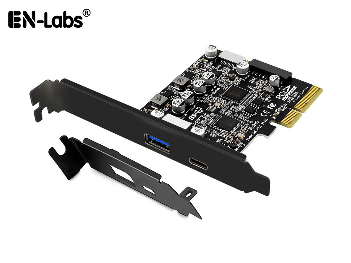
EN-Labs 11-001-366 PCIe x4 USB 3.2 10Gbps 5-port card
- no
- 12CM Case fan,screw…
US$31.99
0.00041077BTC
現貨


ProTechTrader
FM radio breakout covering 76–108 MHz with RDS/RBDS decoding, 3.3 V I²C or 3-wire interface, 3.5 mm jack uses headphone cable as antenna
The ProTechTrader PTT-Si4703 is a development board that adds FM radio reception to microcontroller projects. It serves as a pin-compatible replacement for the SparkFun WRL-12938 V13 board and is referenced in the Make: Radio educational book. Makers and students can use it with 3.3V Arduino, Raspberry Pi, AVR or ARM platforms to experiment with broadcast radio.
The Si4703 chip tunes the 76 to 108MHz FM band and processes both RDS and RBDS data signals. The module operates at 3.3V and communicates via a two-wire I2C interface at up to 400KHz or an optional three-wire system at up to 2.5MHz. Programmable de-emphasis supports 50µs and 70µs standards for regional broadcast compliance.
A 3.5mm audio jack provides the output; inserting headphones or a cable longer than three feet uses the lead as the antenna, so no external aerial is required. The board matches the V13 pinout with GND, 3.3V, SDIO, SCLK, SEN, RST, GPIO1 and GPIO2, though headers are not soldered. Note that the V13 layout swaps the 3.3V and GND positions compared to the older V11 WRL-10663 design.
| Brand | ProTechTrader |
|---|---|
| Model | PTT-Si4703 |
| Part Number | PTT-Si4703 |
Solder the supplied header pins to the board, then wire GND, 3.3V, SDIO, SCLK, SEN, RST, GP101 and GP102 to matching 3.3V logic pins on your Arduino or Raspberry Pi; note that the V13 layout swaps the 3.3V and GND positions compared to the older V11 board.
No periodic maintenance is needed; the board has no moving parts or consumable components, so only re-solder any header joints that become loose over time.
The cable must be longer than 3 feet to act as a sufficient antenna; shorter cables or no headphones connected will cause reception to degrade first during sustained listening.
同類商品
同一分類,同一套結帳流程 — 支援八種加密貨幣,匯率鎖定 30 分鐘。
您支付所用的幣種,以及查看價格所用的貨幣。
結帳時由您的錢包發送
僅供顯示 — 商品目錄以美元計價
查無符合的貨幣。
請選擇網站使用的語言。
查無符合的語言。
初次造訪?
已經有帳戶了嗎?
本店沒有自動重設密碼的機制:由於不寄送電子郵件,也就沒有一次性連結可供申請。只要將地址留在帳戶中,之後將由專人處理。
請求已收到
不會有任何郵件寄到您的信箱 — 本商店完全不寄送電子郵件。會有人親自處理這些申請。
想起來了嗎?